DIY Dummy Speaker Load
I recently finished a build of a Squeezebox with integrated class D amplifier (of which I hope to write more later).
While I still had it on the bench, before putting it into production use, I wanted to run some simple tests, inspired by the great YouTube channel of JohnAudioTech.
A dummy speaker load replaces a speaker with a resistor of similar impedance, so that an amplifier can be run at high volume against a consistent load.
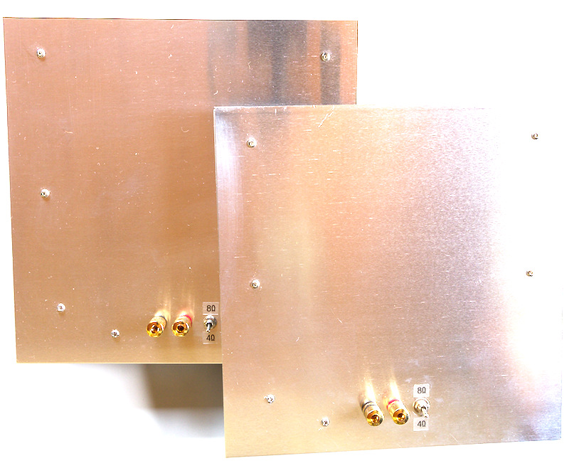
Although I tinker a little bit with cheap amplifier boards, I don’t expect to be doing this sort of thing often, so I didn’t want to go overboard with a sophisticated design. I still hoped to a create a nice, simple and usable tool though.
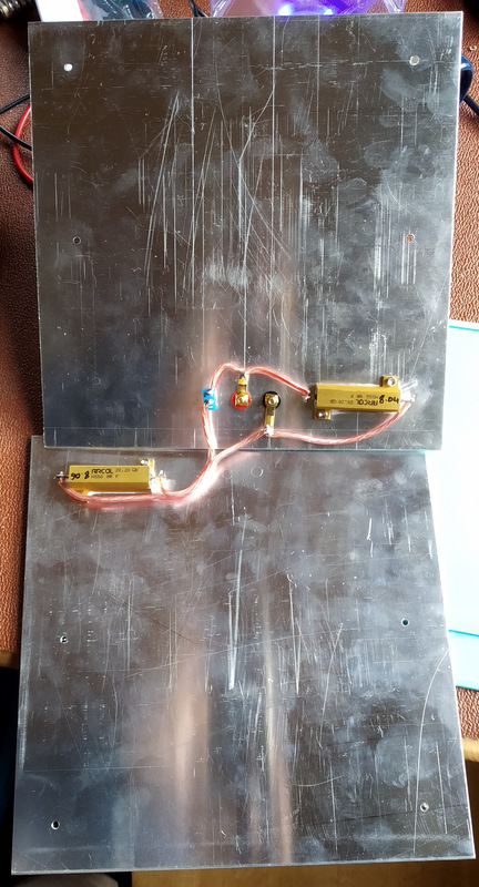
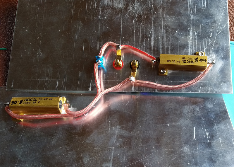
The type of power resistors used in dummy loads can generate a lot of heat when used at high power. I chose 8Ω 50 Watt resistors by Arcol. They are not the special low-inductance resistors that some audio users demand, but I was convinced by various YouTube videos that this would be overkill. I also wanted to be able to test at 4Ω, so I bought four resistors, two for each dummy load. By connecting the two 8Ω resistors in parallel, the resulting resistance would be 4Ω.
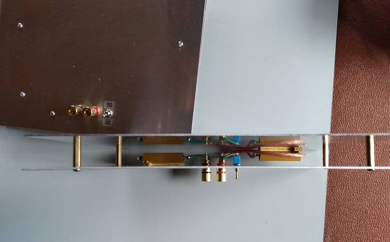
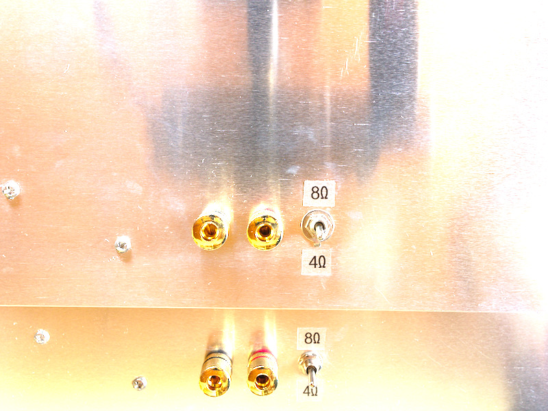
Though rated for 50 Watts, the datasheet shows that the resistors are only rated for 14W without a heatsink, and that a heatsink of 535 cm2 is required to support the full rating. As a heatsink, I purchased for each resistor a 250x250mm sheet of 1.2mm Aluminium. Each dummy load is therefore a sandwich of two aluminium sheets, with a resistor bolted to each sheet on the inside of the sandwich. One resistor is permanenly in circuit across the binding post terminals for an 8Ω load, with the second resistor switchable into circuit for a 4Ω load. It should also be possible to put two resistors in series for a 16Ω test, but it would require a fairly exotic switch to cater for all three alternatives, so I left that possibility out of the design.
